
Part-1 of this modular journey series was about orientating myself into a new modular world. In this part, I’m going to show you the process I went through to actually build all modules.
I started out with the simplest module you can imagine. A passive mult. I bought this one from AISynthesis and is just 8 jacks on a PCB used to split incoming signals to multiple outputs. After that, I build the power supply so I could test the modules I build. All AISynthesis modules are great for beginners so my next two modules were the AI003 Looping Envelope Generator and the AI004 OTA VCF. The instructions for these were easy to follow and all the parts are included with the kit.
Problem #1
My next project was Loosefruit by God’s Box. This was a pretty dense build with a lot of components. The instructions were again easy to follow and with a little patience, I build this module in 2 afternoons. When I wanted to power it up, however, nothing happened. I was afraid I put the ribbon power cable in backward, which is a bad thing to do with Eurorack modules, but that was not the case. The first thing I checked was to measure the voltage on the power inputs. By connecting the red lead of my multimeter to +12v and my black lead to ground, was I really getting +12v? I did the same for the -12V connection which both turned out to be all right.
I then decided to remove the IC’s from their sockets and started measuring if all IC sockets were getting power. All the sockets were fine as well. So what did I miss? I put all IC’s back in their sockets and lo and behold, it powered up with flashy RGB LEDs greeting me. It turned out that the main IC, an Atmega chip also used in the Arduino Uno, wasn’t inserted properly the first time. Lesson learned, always check if your IC’s are fully seated.
The Case
Now that I build a couple of kits it was time to make the case. Luckily my dad is quite handy with everything so he helped me out bending a piece of aluminum into a U shape to form the back, top, and bottom of the case. Two rack earpieces bought at a local metal shop were then connected to the sides and screwed to the Eurorack rails. I bought two 84hp rails from MIDI Amsterdam which are perfect for 19” inch cases.
Ordering Components
Now the difficult part: ordering parts for the Mutable clones. Amazing synth provided a Mouser cart for Yarns and Clouds but not for Plaits, which was just released at the time. Mouser provides free shipping for orders above €50,- so I figured I’d start out with Yarns and Plaits and order the parts for Clouds later. This allowed me to order any parts I forgot or broke later on without paying for additional shipping costs.
I could easily order the parts for Yarns and didn’t even take the time to check it all, which I should have done because a few parts were missing from the Mouser cart. The parts for plaits took me a while to figure out. Not all parts were available on Mouser so I had to order some from Farnell and Reichelt here in Europe. At this time I also ordered parts for the Manhattan Analog DTA.
The only things that are not in the BOM are the jack sockets and some of the alpha potmeters and knobs. But these can be easily ordered from Thonk.
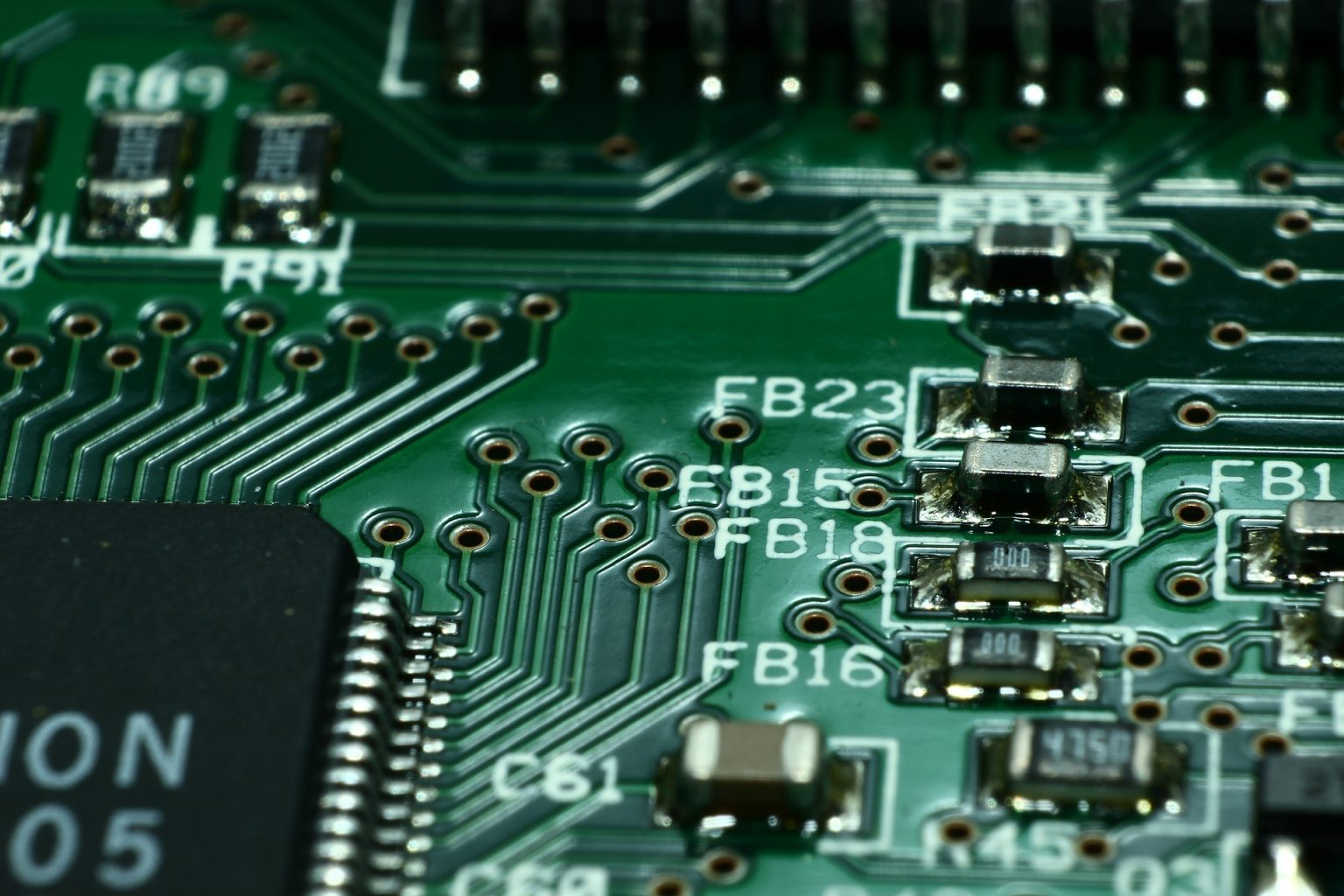
SMD Soldering
When my parts arrived it was time to start with SMD soldering. But before I started ruining the Mutable PCB’s I first practiced with a cheap Chinese SMD soldering kit. A tiny but wide soldering tip is perfect for soldering capacitors and resistors. Most SMD parts are packaged in bags with a piece of cut reel inside. Unfortunately, I lost a few capacitors by opening the reel tape a bit too wildly which sent the parts flying into another dimension never to be found again. The next time I’d make sure to open the tape above a small container to keep the parts together and to prevent them from getting lost.
When soldering through-hole components you usually start with the lowest parts like resistors and diodes and then move up to larger parts like transistors and electrolytic capacitors. The same is true for SMD soldering but it also helps to think about the available space around each component. Therefore it is best to start with the microcontroller unit (MCU) as this requires a technique called drag soldering.
When drag soldering you put a piece of solder on a corner pad and slide the MCU into place when heating up the solder. Just like you do with resistors and capacitors. With one corner in place, you solder the corner on the opposite side. Take your time lining up the MCU pins to the PCB as it’s hard to align later on when all the pins are soldered.
It’s important to check for solder bridges, either with a magnifier, microscope or multimeter. Remove bridges with desoldering braid. If the MCU is misaligned you have to desolder it and start over again. When desoldering there is a risk of lifting a pad which can ruin the whole board, therefore it’s important that you start with the MCU.
Build problems
Of course, I forgot to order a couple of components. With Yarns I forgot to order the encoder. The original one Mutable Instrument’s used is hard to find so I had to get a replacement that rotated the other way around. Luckily there where people before me that changed the code to reverse the encoder direction in software.
In general, I got a lot of help from Facebook groups like Eurorack DIY and Pusherman’s Eurorack DIY Noobs. Also, Adam from Amazingsynth was extremely kind to help me out with the problems I had. With Plaits, my output started distorting after sending a trigger. Someone on the Facebook groups told me to probe around with a cable connected to a speaker and listen to at what point the signal sounded fine and where it went bad. I managed to narrow down the problem to a small group of resistors and capacitors. Adam told me to check the values of these resistors and capacitors which was a good call. It turned out I put a capacitor in the wrong place where a resistor should have been, switching them solved the problem.
On clouds, I had the problem that the texture pot didn’t do anything. I opened up the board and re-heated all solder joints on the path to this potmeter. In the end, it was just a loose connection on the MCU connected to this pot. I did also have a short with clouds which took me a while to figure out but this turned out to be the MCU which was misaligned, and I wasn’t smart enough to check this from the start which would have saved me a lot of troubleshooting.
Flashing the firmware
This part is what scared me the most. I had to download the source code from the Mutable Instruments Github and upload it to the MCU. There are a couple of ways to do this but I decided to use the most stable route which was by using the official ST-Link v2 flashing tool. In conjunction to this programmer you also need a JTAG adapter.
To upload the code you first have to build it by using the Mutable Instruments Dev Environment. Here is a great guide that shows how to do this.
After building the Hex files I used the ST-Link software utility to upload the code. I used Windows for the whole process and everything worked out as smooth as butter. The Mutable Instruments Dev Environment runs on a Linux Virtual Machine however so it should work equally well for Mac users.
Yarns and Clouds could be flashed by using the JTAG connection. Plaits needed SWD to program the MCU which required connecting jumper wires directly to the ST-Link v2. This site has some great pictures on how it’s done: http://www.batguitars.co.uk/
Front Panels
Making front panels turned out to be a lot harder than I thought. I ordered some front panels from Amazingsynth which was just bare brushed aluminum. All holes were drilled but I had to figure out a way to label everything on the panel. I first tried to use the toner transfer method by printing a negative black and white file with a laser printer on glossy paper. I then used an Iron to transfer the Ink to a piece of aluminum that I had laying around. Unfortunately, the ink didn’t transfer completely and although the idea was cool, it was pretty useless. Maybe my iron wasn’t hot enough or my toner wasn’t strong enough but I had to find a better method for labeling my front panels.
The method I ended up using was to buy some printable glossy sticker paper and put it in an inkjet printer. I added some custom backgrounds to the original Mutable designs in Adobe Illustrator and printed out the three designs on sticker paper.
Aligning the sticker paper to the panel was a tough job. I punched two holes with a hammer and a hollow tube and used those holes as an alignment reference. I then cut the sticker paper to size and pulled the protective layer off the top. After aligning the top of the paper to the panel I simply needed to peel off the protective layer and slowly put it in place.
The remaining part was to cut all the holes with hollowing equipment. I used a centerpoint to punch through the small holes and then used a file to remove the excessive sticker paper. After that two layers of clear lacquer where needed to protect the paper from sweaty palms and scratchy fingernails.
In the end, it turned out fine for personal use but I would never want to sell a panel like this. A better way to do this is to buy pre-made panels from Pusherman. These are anodized aluminum panels that look way nicer and save you a bunch of time for a small price.
Putting it all together
After I completed all the modules I had to fit them inside my 19-inch rack. For some strange reason however, Modulargrid calculated a total HP size of 84HP but the total size in real life was 85HP. Luckily I still had some wiggle room and used an extra nut to widen the frame just enough to squeeze out one extra HP.
I did, however, have a bit of a problem with the power supply. I used the PSU from AISynthesis with a 500mA adapter. This power supply isn’t as promising as it looks, however, and couldn’t provide enough power for my whole system. I did notice Endorphin released a new power supply that was just 2HP and included a mult and needed a switching power supply. This provided me with more than enough power for the whole system although a bit more expansive than I originally planned.
In the end, the total cost including the pre-build Erica synth modules and the 2 PSU’s was €1.228. This also includes the solder and tools needed for the job. If I would buy everything pre-build the total cost would be around €1800. Some modules, however, like clouds, are not manufactured anymore so they can only be bought second hand.
So was Eurorack DIY worth it? Definitely yes! I could have saved a bit more money if I ordered the right parts the first time. I have plenty of solder left and I get to keep the tools I bought for the next job which also helps out. But the most important thing is that I learned a ton! I was really afraid that soldering SMD parts wasn’t going to work out as good as I hoped but luckily it did work out fine. I am already thinking about my next setup and I will definitely continue the DIY route in the future.
In the last part of this series I talk about my setup, how it works, and how I use it.